Walk on the wild side? (Seahorse – May 2007)
— 12 Apr 2007
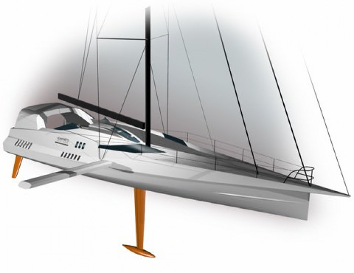
Sliding ballast HYD IMOCA 60 concep
About a year ago we were asked by Offshore Challenges Group to submit a proposal for a new Open 60 design, targeted towards the Barcelona race and the Vendee 2008. Although we have not been putting ourselves forward as mainstream Open 60 designers we have a longstanding relationship with the Cowes-based operation after carrying out the naval architectural work on the Open 60 Kingfisher, and over the intervening years we have supported OCG with various levels of optimisation and IMOCA rule maintenance on the boat, for Ellen MacArthur and later Nick Molony. Not unnaturally we have followed closely the recent trends in Open 60 design, and it was interesting therefore to respond to OCG’s request. It is already well documented that their plan initially was to build two near-identical boats and to seek competitive advantage through exhaustive sail and rig testing, America’s Cup style, perceiving that hull design had pretty well polarised by now.
It follows that a two-boat testing program requires a pair of boats as similar as possible, and bearing in mind the extent of the investment it wasn’t going to make much sense to build anything other than a low-risk, state-of-the-art design. Nevertheless, our interest was not to try to gain this commission by whatever means possible, but to reflect on the class and the direction it has taken, with the benefit of some dispassionate distance.
It will be evident that the concept I will outline here describes anything but a low-risk, state-of-the-art boat. To build one might be considered brave; to build two the gambler’s equivalent to the shirt off his back. Not unreasonably OCG chose to pursue the safety-in-numbers route, and since we were not about to try to sell the concept to anyone else it looked as if the project would be consigned to the ‘bottom-drawer’, a euphemistic term that has grown within my office to mean the repository of good ideas for which the world is either not ready or not prepared to accept. Peter Harken once told me that he and his brother Olaf have one too – in their case it is called the field of broken dreams!
So, bearing in mind that this particular boat is not going to be lining up on the Barcelona start line it is very generous of the Editor to give it some life outside the bottom drawer, and I will do my best here to explain its characteristics and its rationale. This needs to start with a résumé of the context in which it would have found its place.
The modern Open 60 fleet has refined itself into a compact conceptual cluster of super-wide, canting keel boats that can develop exceptional power:weight ratios and support sail plans large enough to overcome what might otherwise be a punitive wetted area. The boats are driven into this generic corner by the Open 60 Rule’s 10 degree provision, which means that a boat with all its stabilizing measures fully deployed – meaning essentially the canting keel and/or water ballast – must not exceed a heel angle of 10° in static, measurement trim, or to be more correct a 20° angle from port to starboard heel tests. This rule had come in years ago as a classic reactionary provision by the rulemakers of the day, configured to deal with what could be seen rather than foreseen. Its effect in the short term was to limit the amount of power that could be derived from water ballast, but in the long term it became a huge design driver which simply encouraged boats to become wider and wider. Why? Because the form stability as described by a yacht’s transverse waterplane inertia sets up an opposing moment to the transverse moment of the canted keel or pressed-up water ballast. So the wider or, in particular, firmer-sectioned a designer makes a boat, the more moment he needs to derive from his canted keel or water ballast to achieve maximum benefit from his 10° allowance. What the rulemakers effectively said was, ‘Make the boat wide and powerful, and we will reward you with even more power through increased transverse ballast moment’. It’s a bit like a supermarket’s ‘two for the price of one’ offer.
With the advent of the canting keel it became possible to achieve the 10° benefit without taking on additional water ballast, so that canted keel boats when pressed were developing more power at less displacement than their fixed keel, water ballasted counterparts. Where a more traditional fixed-keel, water-ballasted boat could score was by having a slightly lighter lightship displacement (no canting keel mechanism), but the performance window in which this matters is so small as to be almost irrelevant, bearing in mind that the boats are powered up so quickly.
With the march of time and the allure of ever increasing power, it has now become a game of canting keels and water ballast. In particular, there is a trick in the IMOCA rule whereby yachts can have offset tanks that do not curtail the yacht’s ability to remain within the 10° constraint. By sitting more or less over the transverse centre of gravity at the 10° heel case – these tanks are benign in their influence on the 10° measurement rule but in reality can contribute greatly in terms of additional, free righting moment when brought to play in breezy conditions, working on the opposite side of their measurement condition of course. And much as it’s good news to have supercharged, superlight boats, there are times when power purchased with the currency of displacement is a pretty useful asset, particularly when there is some moment element to this extra water. This quirk of free offset tankage becomes exponentially better as the boats get ever-wider through the wetted section, because the transverse offset of the centre of buoyancy at 10 degrees increases in proportion to the increased transverse waterplane inertia, and with this revised transverse centre of buoyancy position go the free tanks.
The extent of this trend takes the boats beyond the point where a canting keel can actually bring a boat to 10° in the IMOCA test. Without over-egging the bulb weight, and thus compromising the base displacement of the boat, there is a limit to the moment that can be derived from a canted keel (given that cant angle itself is hard to get much beyond 45° from vertical), and a super-wide boat will generate more transverse waterplane inertia at 10° than a canting keel is able consume, if one can put it that way. Indeed, staying with this consumption metaphor, a designer eager to satiate himself in this feeding frenzy that is the Open 60 power game can really go to town on these offset tanks. With some residual angle available beyond the canting keel’s exertion, these tanks can be charged up in volume and offset to take the boats to a whole new level of power.
It’s an interesting game and though these are the unintended consequences of a somewhat naïve rule, it does not change the fact that these are fascinating machines. But is that it? Is this the final conceptual destination? I’m not so sure. Over the years I have felt that there is a paradox within the current path – the power inherent in a canting keel is delivered only by dragging this stabilizing device through the water, generating increased drag in that it requires an additional appendage to deal with the conventional hydrodynamic demands of sideforce generation. This is a double-whammy in terms of wave-making and viscous drag. No high performance sailing dinghy drags its stabilizing device through the water but through a medium far less dense – air.
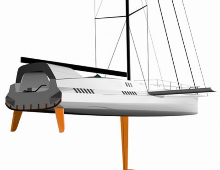
Is there a way within the Open 60 rule to create a boat that has all the power of the canting keel monsters but without relying on the contribution of a canting keel? It is an intriguing thought and after a considerable amount of naval architectural work the result finally manifested itself in what became our submission to Offshore Challenges Group – a fixed keel design with the equivalent of an International Canoe’s sliding seat. As one might imagine there are a number of technical obstacles as well as a raft of rule challenges that have to be met, and some serious work would have had to be done to take the project from its embryonic stage to a fully-buildable boat. But by taking a holistic approach to the problem a path emerged through the labyrinth of design challenges and rule prescriptions, leading to what seems to be a cohesive and viable concept – if a little strange at first sight.
The essence of the project is a hybrid mix of keel- and deck-ballast; of form stability through the sailing heel angle range and buoyancy distribution through the large angle range, with free-flooding volumes and downflooding points designed to kick in at particular heel angles. It is a complex piece of naval architecture that does not employ valves or similar devices, just natural ballasting modes which switch automatically from one to another in the process of the roll.
There are particular heel cases that stand out in the consideration of an Open 60 design, some of them rule-defined and others of particular performance interest. These are:
- The 10 degree inclining case, already discussed at great length, which is the most overt rule driver and which defines the power of the boat and ultimately its performance potential through definition of its power to carry sail (Rule D.2.)
- The worst-case capsize angle, when everything is caught on the wrong side. Boats are required to have an angle of vanishing stability AVS of >108° in this condition (Rule D.4.)
- The ‘conventional’ capsize case, with all ballasting centralised, where the AVS is required to be >127.5° (Rule D.3.).
- A more general requirement that the ratio of positive- to negative-areas of the GZ curve must exceed 5, a demanding qualification that alludes to the energy required to capsize and/or recover a boat (Rule D.3.)
- A requirement that a boat must, by its own ability or the ability of the crew to influence events, be capable of righting itself from complete inversion without outside assistance (Rule D.1.).
- The sailing range, typically up to about 20° in an Open 60, although 20-30 still warrants consideration.
In general terms the foregoing rule environment has been constructed as a fit to that which can be achieved by the ‘state-of-the-art’ wide beam, canting keel concept, and as such it forms a strong typecasting constraint on future potential development in this idiom. That said, the prescriptions do not necessarily exclude other genres as long as they are able to meet the particulars of these requirements.
The Open 60 Rule is unusual in that it does not have a ‘spirit of the rule’ clause in common with most other rating rules. Furthermore, it is explicit in stating that anything not expressly forbidden is permitted; this, it defines, is the ‘open’ nature of the rule. Thus one does not have to feel compelled to analyse the problem through the same microscope as the rulemakers, or, for that matter, one’s competitors..
The concept we have explored as a performance advance on the status quo can best be described in the context of the various foregoing rule and performance markers.
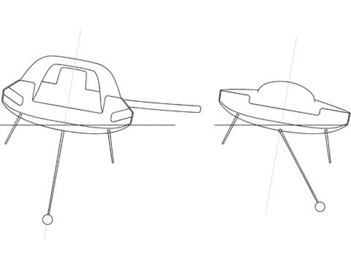
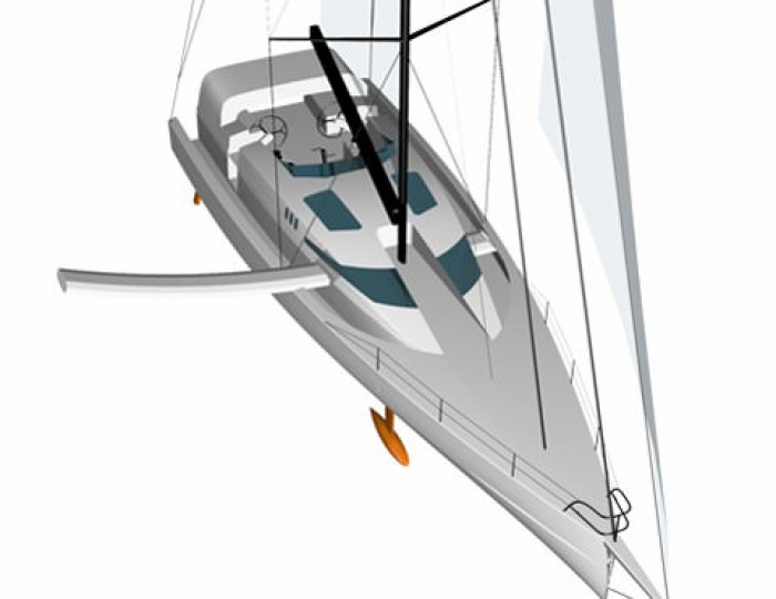
- For the 10° inclining case the boat is presented as a fixed-keel boat with a ballasted deck spar or beam, projected to its maximum extension. What holds good for the current fleet – more beam equals more power – holds good here also, but unlike the canting keel arrangement which is ultimately limited by maximum cant angle, there is no practical limit to the projection of the spar. Thus even on a super-wide boat the full 10° can be accounted for by the moment exerted by the ballast spar. DRAWING SHOWING 10 DEGREE COMPARISON
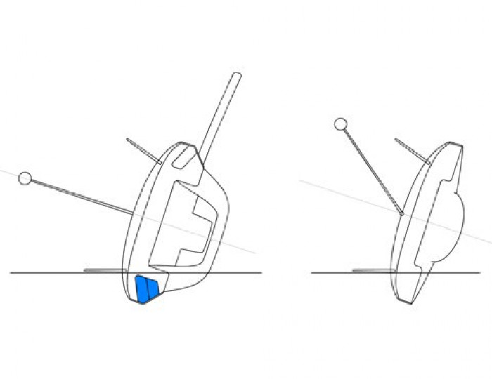
- The ‘worst case’ capsize angle will be with the lead ballast fully extended within the deck spar or ballast boom, and the boat caught aback or forced into an all-standing gybe. The aggregate centre of gravity location of the deck ballast and the fixed centreline keel is not very much different to the CG location of the canted bulb keel. What difference there is is more than made up for by the free-flooding chambers built into the extremes of the boat, combined with the configuration of the rather unusual coachroof which presents buoyancy just where it is most required through these large angles of heel. These chambers use the naval architectural term ‘downflooding’ in a positive way, and without any pro-active influence the juxtaposition of floodable volume and offset coachroof buoyancy gives the boat the characteristics of a much slimmer, higher freeboard boat in this range. In effect, the centre of buoyancy migrates away from the centre of gravity faster than it would on a conventional boat, so a positive righting arm is preserved for longer. As far as rule legitimacy is concerned the free-flooding chambers could not be described as tanks for 10° compliance since they are open ended at the transom and are as incapable of withholding water as an open-transom cockpit. In fact another variant of the concept (see Figure xx) is a more conventional hull with a substantial outer walkway, for want of a better description, which is open aft to the sea. This does the same job. And just to tidy up the features relevant to this capsize case, it should be pointed out that the deck spar is also free-flooding so that its structure is almost neutrally buoyant through this range. The downflood apertures in the spar are carefully places to gain optimum advantage, but that’s just a small detail in the scheme of things.
- The requirement of Rule D.3., which calls for an AVS >127.5°with all the ballast centralised, necessitates the preservation of adequate bulb weight to neutralise the negative moment of the deck ballast block in capsize conditions. The appropriate relationship between bulb weight and deck ballast combines with the free-flooding chambers and offset coachroof buoyancy to ensure comfortable compliance with this provision.
- A complete GZ curve for this boat is effectively a sequence of varying buoyancy distribution throughout the rotation range, with inflections and discontinuities in the GZ curve as downflooding occurs, and finally with the influence of a buoyancy hoop at the aft end (as I developed for Kingfisher, but more on this later). The combined geometry enables the boat to meet the rule’s ratio requirement of 5 quite comfortably.
- The crew will need to be able to manipulate the lateral position of the ‘deck’ ballast from within the boat so that it can be cranked out to port or starboard as required. The resulting ballast moment combines with the unusually low inverted transverse waterplane inertia (due to the combination of buoyancy pod, tumblehome, free-flooding side chambers and free-flooding ballast spar) to enable the boat to meet this rule requirement.
Other performance characteristics
The fixed keel has a number of advantages over its canting keel counterpart, all other things being equal in terms of stability. The effective span and aspect ratio of the hydrodynamic lifting surfaces are significantly greater for the fixed keel configuration. Based on a typical close hauled sailing condition with 15-20 degrees heel, an improvement in effective draft of over 80% seems likely over a canting keel configuration with keel fully canted and daggerboard fully immersed. This improvement in effective draft has a significant effect on induced drag and adding this to the reduction in wetted area we are looking at considerable drag savings.
The IMOCA rule states that the keel may only have one axis of mobility, which offers a further benefit to the fixed keel configuration in that a trim tab may be used. Because of the relatively extreme beam of the boat and its eccentric axis when heeled the ability to reduce leeway when close hauled will be of great benefit as this will enable the vessel to align itself straighter to the water flow, resulting in further drag reductions.
Another performance benefit that comes with the package is a design choice ability to power up the boat to a realm not seen even by a watered-up canting keel boat. Picture the sliding ballast boat in the 10° measurement condition and you will note that the fin and bulb ballast is working in opposition to the sliding ballast. Increase the bulb weight by a tonne, for argument’s sake, and the boat will reduce its heel from the 10° threshold to about 8°, requiring the sliding ballast moment to be increased in turn to bring the boat back to the allowable 10°, either by increasing the sliding ballast weight or the moment arm. Thus one could take a strategic view of one’s position relative to the fleet in general, choosing one’s preferred position with respect to displacement versus power with somewhat more freedom than is possible in a canting keel boat.
One self-evident compromise in this sliding ballast design is the peculiarity of the deck layout, driven by volumetric aspects more concerned with rule compliance and fitness for purpose rather than for the last word in contemporary state-of-the-art deck design. Here one has to borrow the word ‘open’ from the class title and attach it as a prefix to ‘-mindedness’. The best sailors, in general, just want a level playing field with their competitors – a slight edge maybe but not usually outlandish risk and non-conformity. So, accepting that this one would be a very hard-sell the only way to contemplate it is to distance oneself from conventional wisdom and then a logic does emerge. The work-in-progress solution is a very protected domain, with a foredeck designed to make re-emergence from occasional bow-burying easier, and a bulwark of sorts to protect the crew from awkward cross-seas.
In the preferred concept design, access to the sides of the boat is more difficult than normal, to attend to sheet leads, etc, but then the sidetrench variant (Figure xx) offers an optional solution to this. Of course, one thing is very certain in this sphere of work, one does not detail these boats without close liaison with the crew who will sail them, and since this has effectively turned into an academic exercise who knows where the detail deck design would have lead.
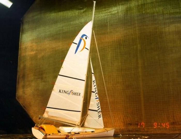
Another feature of the boat that warrants some discussion is the windage inherent in the concept, and here I have been encouraged by wind tunnel work we carried out during the Kingfisher development phase. I was keen to explore the potential of a buoyant hoop in the design of that boat and in consequence needed to evaluate its air drag, to see whether its viability would close or open doors. In the event we did not pursue it but the following summary from the Wolfson Unit Wind Tunnel report is interesting.
‘The results show that there is no discernible performance loss with the addition of the hoop, indeed at 35° apparent wind angle the hooped configuration has higher driving force. This may be due to improved sail trim rather than any inherent aerodynamic improvement, but these results serve to demonstrate that the hoop need not affect performance, and may with careful design offer a beneficial influence to the sail forces by sealing the gap between boom and deck.’
Obviously, if this project had progressed beyond proposal stage one of our first visits would have been to the wind tunnel. In this work now I have taken my original Kingfisher hoop to a larger volume, but am still confident that the windage properties of this boat are not a project door-closer. Figure xx shows a typical wind’s eye view at 25 degrees of heel and at 30-40° apparent, comparing our concept boat and a more conventional Open 60.
A cornerstone of this project is the ballast beam itself, and it may be interesting to point out that there were a number of options under consideration. The preferred choice is a sliding beam carrying the lead slug on an internal track. This would have had the slight complexity of a double action haulage system, but at least it would not intentionally be deployed to leeward (except to induce heel in very light airs).
Another option was a full beam and a single action ballast carriage, with some facility to rock the beam so that the ballasted, windward projection would automatically stay low and rotate the leeward projection upwards to keep it out of the water as best as possible.
A third option was a variant of the full beam but with a break and hinge in the beam so that the leeward side could be hauled up on a halyard, and well out of water’s way. Achieving smooth continuity in the beam would not be a problem and the lead slug would itself have a wheeled undercarriage, so no problems with discontinuous tracks.
A fourth consideration was a ballast boom, rotating under the main boom and pivoting about an independent pedestalled gooseneck. In many ways this would probably be the simplest, lightest solution which could be controlled by foreguys and afterguys. However, unless the lead slug could be guaranteed to be drawn in against the boom’s gooseneck in a tack or gybe we deemed that it would be in contravention of Rule D.3 (AVS >127.5° with ballast centralised), as the aft end of this boom needed to clear the aft hoop, and the lead slug in this aftermost, uplifted position would have given the boat too high a VCG for the D.3 provision.
Finally, and perhaps the most obvious choice, we considered tying the ballast beam into a deck spreader arrangement. This is fine in principle and would be developed as an arced track and tunnel running within a fairly complex composite structure. The biggest downside is that the lead in its offset position would be carried quite high, although that’s not a big deal bearing in mind the benefit of the long transverse lever.
How, the reader might ask, does the ballast beam arrangement square up against IMOCA prescriptions? Well, perhaps unsurprisingly, the Rule has little to say about such an arrangement. In Section D of the rule we have the words, ‘Any shifting of weight with the aim of altering control or stability is permitted within the limits fixed by current rules’, and C.5.4 states ‘In a change to rule 50.3 of the RRS, the use of outriggers is allowed’.
However, we see that in B.9, ‘Sea water Ballast’, ‘All ballast tanks shall be integral to and within the hull’. So, sadly, we cannot use replenishable water as our outrigger righting medium, which is just as well because that would have given the concept an outrageous advantage.
The only rule provision we feel could give us something to argue over is rule B.1, ‘Flotation plane at rest or under sail remains continuous in its transversal section’. This could be interpreted to mean that the outrigger extremity must never be immersed, but then that would also need to be the case for the ubiquitous deck spreader, or any other outrigger invited by rule C.5.4.
There are other aspects of the design that are unusual but not specific to the unorthodox ballasting concept of this boat, and as such are transferable to other projects. Essentially these relate to high speed sailing, making the connection with power boat design, with many of these ideas stemming from extensive R&D work carried out on our 37 metre, high performance motor yacht currently nearing completion at McMullen & Wing, New Zealand. The first, most obvious display of this morphed thinking is the spray rail forward, both on the hull itself and under the sheer. One is somewhat limited by considerations of light air upwind sailing in the extent to which one can run a decent spray rail on a sailing yacht, but even if one restricts oneself to what might ordinarily be considered to be the dry zone of the forebody there is enough potential rail length to help shed water downwind at speed, and to generate some lifting surface to help prevent bow burying. It is surprising to me that these have not yet appeared in Open 60 design – after all there is no no-hollows rule as such, merely a provision that requires the hull at any transverse section to keep travelling downwards as it runs from sheer to centreline. And not all sprayrails kick up on themselves.
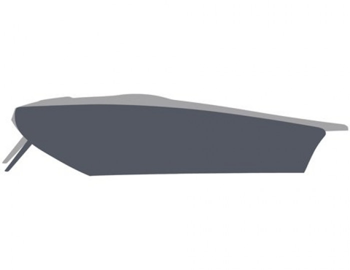
The other, more interesting feature of the design is the interceptor aft, which is a huge subject in itself. In 1992 I ended up with spare tank time when testing a model for the Whitbread 60 Dolphin and Youth project, and although trim tabs were not allowed by the rule I was intrigued to see what benefit might be derived for such a boat. The result was very promising indeed, and was instrumental in my late choice to go for a transom rudder to try to seek some proportionate benefit. Some ten years later Angus Blair, a full time member of our team, asked whether I could propose a subject worthy of study for his MSc Naval Architecture thesis, and I had no hesitation in proposing trim tabs and trim control for fast sailing yachts.
In his research he very soon found himself considering interceptors as well as trim-tabs or wedges, and being just simple, retractable blades that intersect the waterflow, their potential ease of application and lightness was appealing in itself. Both showed significant benefits, but in general the results showed iterceptors to be far more efficient through the sailing speed range these boats are subjected to.
Without wanting to give too much information away, it became evident from the towing tank that the interceptors reduced drag considerably through the speed range of 8-20 knots, with impressively large reductions through hump speed – up to 20% drag reduction in fact, bringing on an early transition to the planing regime. Obviously one would want to carry out a robust CFD programme and go back to the tank with more serious resource were this to be implemented at full scale, but clearly there’s no smoke without fire. It’s interesting how materially the trim is manipulated by relatively small interceptor depth changes, and significant also how the increased wetted length when trimmed does not necessarily bring with it a net increase in wetted area, bearing in mind the changes in the wave profile aft over the three images.
One of the things we saw in CFD work carried out by W.S. Atkins for the Kingfisher project was that when the trim was changed to induce squatting by the stern, the thickness of the boundary layer was compressed, altering the pressure distribution over the aft end of the hull and improving the efficiency of the rudders. It seems plausible that the change in pressure distribution brought on by the interceptors could also improve rudder efficiency, but without the squatting.
Clearly interceptors are devices that can be retro-fitted to boats, but there are nuances there which would manifest themselves best in a hull designed for the purpose. In this respect one would be considering slightly increased rocker aft than normal, so one’s default position might be with the interceptors partly projected. The range of travel would be such as to exert the maximum trim control required, to a fully retracted condition where one was able to induce a squatting tendency in the wildest conditions, or in very light airs of course when one is trying to minimise transom immersion. One thing seems clear to us, interceptors are powerful tools requiring a pro-active retraction system that is quick to manipulate. It may be a case of leaving the steering to the autopilot while the helmsman plays the boat trim.
Performance analysis
Putting the interceptors and trim control to one side, what performance gain is one likely to see from an Open 60 with a sliding ballast concept, as opposed to a canting keel arrangement? To draw some sensible comparison we designed two boats of the same beam and form stability, sharing the same general hull configuration with a chine running aft and a maximum beam at the upper end of the contemporary spectrum. The ballasting conditions were set by the 10 degree rule, with the projected sliding ballast producing exactly the same righting moment at 10 degrees as the canting keel boat with keel fully canted.
Running both through the VPP and our weather model, based on over 10 years of statistical wind data, the indication is that the Vendée course favours the sliding ballast boat to the tune of just over two days, as I say without taking into account the potential gain of the interceptors. On the Transat Jacques Vabre course the gain in favour of the sliding ballast boat seems to be just over 8 hours.
It has been a funny project this, intensely interesting but squeezed in between other projects that need to get built. Having designed boats for various round-the-world formats over the years it is disappointing in many ways that this boat is not going to be lining up with the others at the Barcelona start or at Les Sables d’Olonne, but then again one can luxuriate in the unusual circumstance that this is esoteric design without responsibility! No lying awake at night, wondering what the next Southern Ocean front is going to do to one’s creation and, more particularly, its driver. Nor, for that matter, any anguish expended trying to defend the boat from the rulemakers’ probable desire to protect the status quo
